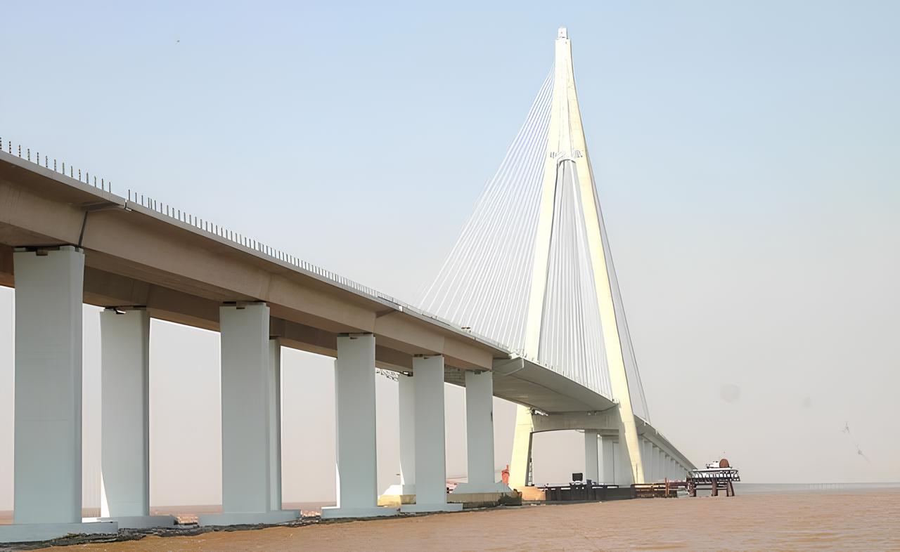
The "simply-supported-first-then-continuous bridge structure" refers to a system where two or more spans of prestressed concrete beams are precast as simply-supported beams and then connected by cast-in-place concrete to form a continuous structural system.

1.High rigidity, minimal deformation, fewer expansion joints, and improved driving comfort.
2.Prestressed tendons in the simply-supported girders are tensioned in the factory, while the tendons in the negative moment zones (over supports) are installed and tensioned on-site. This reduces construction equipment requirements and avoids ground obstructions caused by tendon tensioning.
3.Precast girders can be standardized, enabling factory-based mass production and management. This improves technical efficiency, reduces construction time, and enhances economic benefits.
(1)Prefabrication of the main girders. After the concrete reaches 100% design strength, tension the prestressed tendons in the positive moment zones (mid-span), perform grouting, and clean the vent holes on the girder bottoms (for prestressed concrete simply-supported-to-continuous box girders).
(2)Set temporary supports and install permanent Supports. Erect the main girders span-by-span on temporary supports in a simply-supported state. Connect the bridge deck reinforcement and crossbeam reinforcement promptly.
(3) Connect reinforcement at the joint segments, install corrugated pipes for joint tendons, and thread the tendons. Cast the continuous joint concrete, mid-crossbeams, and the corresponding bridge deck concrete (within the same length as the top slab tendons) during the lowest daily temperature (not exceeding +15°C). After the concrete reaches 100% design strength, tension the top slab tendons and perform grouting.
(4)After the joint is completed, pour the remaining integral bridge deck concrete from the mid-span to the supports. After the pouring is completed, remove the temporary supports within a unit to complete the system transformation. When removing the temporary supports, special attention should be taken to prevent high temperatures from affecting the quality of the rubber supports.
(5)Spray waterproofing layers, install expansion joints, and proceed with bridge deck construction.
(1)Precast T-girder concrete must reach 100% design strength before tensioning prestressed tendons. The tensioning sequence is: Tendon No.1 → No.4 → No.2 → No.3. The two strands of Tendon No.1 must be tensioned simultaneously to prevent lateral bending of the girder. During construction, measure the friction coefficient (μ) between tendons and ducts, the duct deviation coefficient (k), and the anchorage seating loss (σₘ). The actual tensioning control stress (σₖₘ) is the sum of σₘ and the design control stress (σₖ).
(2)End reatment of box girder joints. The joint ends of box girders are typically designed as stepped "horse-hoof" shapes to ensure efficient force transfer and meet construction requirements. Dimensions and step details are reserved based on operational needs.
(3)Temporary Support Design. Temporary supports must bear girder loads and allow easy dismantling. Common methods include:
Sulfur mortar temporary supports with embedded electric heating wires. These are removed via electrical heating during system transformation.
Sandbox-type temporary supports using steel tubes, hardwood, or prefabricated reinforced concrete blocks. The settling of the sandbox supports must be tested during girder erection and their height adjusted by sand filling or cover plate modification to accurately control girder elevation.
(4)The construction of cast-in-situ concrete in continuous sections. The connection of reinforcement in the cast-in-situ continuous section can be achieved through lap welding or strip welding. The cast-in-situ concrete section uses the same grade of concrete as the beam and slab. To prevent the cast-in-situ continuous section concrete from cracking during the curing and hardening process, which would affect the bearing capacity of the concrete during the secondary tensioning process and the overall mechanical performance of the bridge, a micro-expansion agent is added to the cast-in-situ continuous section joint concrete. The gap between the permanent rubber support and the bottom formwork is padded and sealed with a rust-proofed steel plate or a sand box made of bamboo plywood to prevent grout leaks.
(5)The secondary tensioning of the negative moment is to tension the prestressed steel tendons on the top surface of the beam and slab, which is the crucial step distinguishes simply-supported-first-then-continuous bridges from standard simply-supported bridges. High-strength, low-relaxation steel strands are used for stressed steel tendons. The steel tendons are tensioned simultaneously from both sides. working outward to inward. One steel strand is tensioned each time until it is fully tensioned. The grouting work should be carried out in a timely manner after the tension is completed.
The simply-supported-first-then-continuous structure combines the simplicity of prefabricated girder construction with the structural benefits of continuous bridges. It enhances the load-bearing capacity, reduces expansion joints, and minimizes transverse deck cracks. As construction techniques advance, this method is becoming increasingly popular for its efficiency and quality. In next article, we will discuss quality control measures for such bridges. Stay tuned and feel free to reach out to us for further discussion!

International Department: Room 2211-2212, Tower C of Wanda Plaza, Tongzhou District, Beijing 101118, China.
+86-13021287080
info@boyoun.cn